V. 2D Portal Reactions Sidesway 1
To find the displacements at the nodes of a frame due to movements of supports.
Reference
C.K. Wang, Intermediate Structural Analysis, International Student Edition, 1983, McGraw Hill, Section 2.11, p47.
Problem
Calculate the deflections at node B and support D.
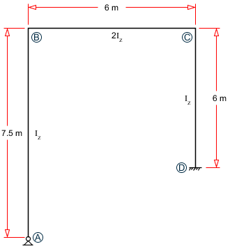
Frame subject to imposed displacements
Load Cases:
- Vertical displacement of 1 cm at Node A
- Vertical displacement of 1 cm at Node B
Comparison
| Result Type | Theory | STAAD.Pro | Difference | Comment | |
|---|---|---|---|---|---|
| Load Case 1 | Horizontal displacement at node B (cm) | 1.25 | -1.25 | none | Different orientation of positive axis results in different sign. |
| Rotation at node B | 0.001667 | 0.0017 | none | ||
| Horizontal displacement at node D (cm) | 0.4167 | -0.4167 | none | Different orientation of positive axis results in different sign. | |
| Load Case 2 | Horizontal displacement at node B (cm) | 1.25 | 1.25 | none | |
| Rotation at node B | 0.001667 | 0.0017 | none | ||
| Horizontal displacement at node D (cm) | 0.4167 | 0.4167 | none | ||
STAAD Input
The file C:\Users\Public\Public Documents\STAAD.Pro 2023\Samples \Verification Models\03 Frames\2D Portal Reactions Sidesway 1.STD is typically installed with the program.
STAAD PLANE DEFLECTIONS DUE TO MOVEMENT OF SUPPORTS
START JOB INFORMATION
ENGINEER DATE 17-Sep-18
END JOB INFORMATION
*
* REFERENCE: INTERMEDIATE STRUCTURAL ANALYSIS, C.K.WANG
*     INTERNATIONAL STUDENT EDITION, 1983, MCGRAW HILL
*     SECTION 2.11, PAGE 47
*
UNIT METER KN
JOINT COORDINATES
1 0 0 0; 2 0 7.5 0; 3 6 7.5 0; 4 6 2.5 0;
MEMBER INCIDENCES
1 1 2; 2 2 3; 3 3 4;
UNIT CM KN
MEMBER PROPERTY AMERICAN
1 3 PRIS AX 2400 IZ 720000
2 PRIS AX 4800 IZ 1.44e+06
DEFINE MATERIAL START
ISOTROPIC MATERIAL1
E 2171.84
POISSON 0.17
END DEFINE MATERIAL
CONSTANTS
MATERIAL MATERIAL1 ALL
SUPPORTS
1 PINNED
4 FIXED BUT FX MZ
LOAD 1
SUPPORT DISPLACEMENT LOAD
1 FY -1
LOAD 2
SUPPORT DISPLACEMENT LOAD
4 FY -1
PERFORM ANALYSIS
LOAD LIST 1
PRINT JOINT DISPLACEMENTS
LOAD LIST 2
PRINT JOINT DISPLACEMENTS
FINISH
STAAD Output
   JOINT DISPLACEMENT (CM   RADIANS)    STRUCTURE TYPE = PLANE
   ------------------
 JOINT  LOAD   X-TRANS   Y-TRANS   Z-TRANS   X-ROTAN   Y-ROTAN   Z-ROTAN
      1    1     0.0000   -1.0000    0.0000    0.0000    0.0000    0.0017
      2    1    -1.2500   -1.0000    0.0000    0.0000    0.0000    0.0017
      3    1    -1.2500    0.0000    0.0000    0.0000    0.0000    0.0017
      4    1    -0.4167    0.0000    0.0000    0.0000    0.0000    0.0017
   ************** END OF LATEST ANALYSIS RESULT **************
    38. LOAD LIST 2
    39. PRINT JOINT DISPLACEMENTS
  JOINT    DISPLACE
      DEFLECTIONS DUE TO MOVEMENT OF SUPPORTS                  -- PAGE NO.    4
   JOINT DISPLACEMENT (CM   RADIANS)    STRUCTURE TYPE = PLANE
   ------------------
 JOINT  LOAD   X-TRANS   Y-TRANS   Z-TRANS   X-ROTAN   Y-ROTAN   Z-ROTAN
      1    2     0.0000    0.0000    0.0000    0.0000    0.0000   -0.0017
      2    2     1.2500    0.0000    0.0000    0.0000    0.0000   -0.0017
      3    2     1.2500   -1.0000    0.0000    0.0000    0.0000   -0.0017
      4    2     0.4167   -1.0000    0.0000    0.0000    0.0000   -0.0017